Proper Field Technique with Sight Glasses and the Importance of Field Observation

By Andrew W Sloley
Contents
Take care when interpreting sight glass readings
Field technique with sight glasses
Purge systems to keep sight glasses and level instruments in service
Checking foaming or condensation with a sight glass
Field observation identifies restricted range problems
References
Take care when interpreting sight glass readings(Return to Contents)
 Sight glasses are an invaluable tool for troubleshooting towers and checking instruments. However, they can lead the unwary down trails to false conclusions. Make sure you understand the system. Then apply the fundamentals of how sight glasses work as DP instruments rather than jumping to the conclusion that they must always show the liquid level inside the tower.
Field technique with sight glasses(Return to Contents)
Correct field technique minimizes the probability of getting poor data. Inaccurate data is worse than no data. No data forces you to make a judgement or to look for alternate methods. Inaccurate data leads to the wrong conclusion: ineffective decisions: and wastes money and time.
Correct field technique when using a sight glass is to:
- Block the glass from the service.
- Drain the glass.
- Open the bottom block.
- Open the top block and let the sight glass fill from the bottom.
- Observe sight glass conditions.
This assures that the liquid in the sight glass is the same liquid as in the tower. The color of the liquid in the sight glass should also be compared against the expected color of the liquid from the tower. If the sight glass is on the bottoms of a crude oil fractionator, it should be black. A clear liquid in the sight glass shows that something is wrong.
Purge systems to keep sight glasses and level instruments in service(Return to Contents)
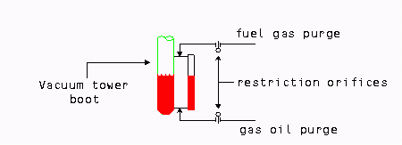
In other situations, inability to drain the sight glass reveals problems. Process liquids can set. An apparently constant level in the sight glass may come from cooled liquid solidifying rather than from tight level control. A common service for this is refinery vacuum column bottoms. Sight glasses, and external level instruments, often plug solid. Keeping the sight glass in service requires a purge system. Figure 1 shows a good purge system for this service. Fuel gas purge keeps the upper level tap clear and a gas oil purge keeps the lower level tap clear.
Checking foaming or condensation with a sight glass(Return to Contents)
Opening the bottom block of the sight glass, then opening the top block assures that the sight glass fills with liquid from the vessel. This gets around problems of condensation filling the sight glass with lighter liquid and giving a false reading. However, the standard procedure still suffers from all the problems of inaccurate levels with foam in the column. Reversing the valve opening procedure gives us a way to check if foam is inside the vessel. The alternate sight glass technique uses the following steps.
- Block the glass from the service.
- Drain the glass.
- Open the top block.
- Wait and observe if liquid starts to accumulate in the sight glass.
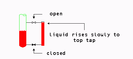
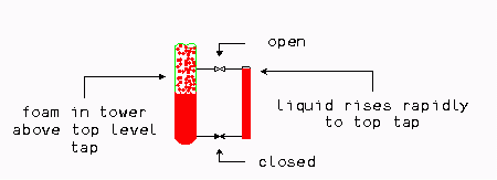
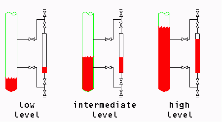
With condensation, liquid will build up gradually in the sight glass. Eventually, the level rises to the level of the top tap (Figure 2). With foaming, the liquid level will rapidly rise to the top of the sight glass (Figure 3). Of course, foaming and condensation can occur together but the rapid rise in level from foam outweighs the condensation effect.
Field observation identifies restricted range problems(Return to Contents)
Inaccurate information that fools our control system often fools us as well. When troubleshooting, we often use the same data the control system uses. Our judgement allows us to interpret the data differently, or even ignore it. Interpretation and judgement choices depend upon our knowledge of the process, understanding of fundamentals, and of how equipment works.
One common problem with both sight glasses and level instruments is restricted range instruments. This is more of a problem with sight glasses, displacement level sensors, and float level devices than with DP cells. Details of how the problem can affect DP cells will be covered in a future column.
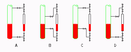
Figure 4 shows a four different sight glass installations. The same type of connections could be made for external wells required for displacement or float type level instruments. Only the first installation shown in Figure 4, ‘A', is correct. All the others suffer from a restricted range defect. ‘B' has restricted range on both ends, ‘C' has restricted range on the low level end, and ‘D' has restricted range on the high level end.
As long as the liquid level remains in the center of the level instrument (or sight glass), between the level taps, then the instruments read correctly. Problems begin when the level goes outside the range between the sight taps. Figure 5 shows the indicated versus actual levels for the restricted on both ends configuration (‘B' configuration from Figure 4). With a liquid level below the lower tap, the seal leg in the instrument connection traps liquid in the sight glass or level instrument. The sight glass or level instrument shows a false high level. With a liquid level above the upper tap, the seal leg in the instrument connection traps vapor in the sight glass or level instrument. The sight glass or level instrument shows a false low level. Depending on the system and liquid levels in the vessel, condensation, vaporization, or compression of the vapor space can also change the level in the sight glass or instrument.
Field observation, going out and checking the sight glass or level instrument allows us to look at the connection and see if it is made correctly. No amount of troubleshooting in the control room identifies incorrect instrument installation. The author has seen many variations of restricted range instruments. Problems of restricted range sight glasses and level instruments are common. In fact, they are sometimes considered a ‘classic' reason for field troubleshooting.
With restricted range instruments, we are asking the instrument to do the physically impossible. The noted safety expert Trevor Kletz, talking about this very problem [1], summarized the situation perfectly:
is that they violate the laws of physics…."
Attempting to use instruments that violate the laws of physics gives improper data to control systems and confuses troubleshooting. Understanding how the instrument works, how it must be connected, and how to interpret the readings is critical for profitable operation.
References(Return to Contents)
[1] Kletz, T. A. Plant instruments: which ones don't work and why. Chemical Engineering Progress, July 1980: 68-71. Figure 1 in Kletz's article is the restricted range problem shown. Figure 1 has an error, it should be rotated 90 degrees clockwise.
About the Author(Return to Contents)
Andrew Sloley is a consultant in distillation and troubleshooting. He worked as a troubleshooter and consultant for Glitsch, Inc. from 1990 to 1995 and for an engineering company between 1995 and 1999. Previously, he worked as a process engineer in technology development and application for Exxon Chemicals. His experience covers a wide range of petroleum refining and petrochemical areas. He has authored or co-authored over 90 publications and conference papers. Papers have appeared in Oil and Gas Journal, Hydrocarbon Processing, Petroleum Technology Quarterly, Chemical Engineering Progress, Hydrocarbon Technology International, National Engineer, and others. Conference papers have included presentations at the National Petrochemical & Refiners Association, American Institute of Chemical Engineers, American Society of Mechanical Engineers, Japan Society of Mechanical Engineers, Chemical Engineers Australia, and others. He currently acts as a consultant to a variety of companies in the area of troubleshooting and distillation. Other current work includes both engineer and operator training for distillation operations, design, and troubleshooting. Sloley has a bachelor's degree in chemical engineering from the University of Tulsa, and is a registered professional engineer in the State of Texas. He resides in College Station, TX, and can be reached at asloley@distillationgroup.com or tel: 979-764-3975 (www.distillationgroup.com).
